> ## Documentation Index
> Fetch the complete documentation index at: https://aegean.ai/llms.txt
> Use this file to discover all available pages before exploring further.
# Planar motion representations
> Frames, rotations, rigid-body configurations and twists in the plane, the background for wheeled robots.
This section borrows heavily from chapter 3, Rigid-Body Motions, of Kevin Lynch and Frank Park, *Modern Robotics: Mechanics, Planning, and Control* (Cambridge University Press, 2017). You can [download the chapter as a PDF](https://artifacts.aegeanai.com/pdf/lynch-mr/body-motions.pdf).
This section covers rigid-body motion in the plane. A planar rigid body has three degrees of freedom: two for position and one for orientation. Every idea here has a direct counterpart in three dimensions, covered in [spatial motion representations](/aiml-common/lectures/kinematics/spatial-motion/index). Wheeled robots move in the plane, so this section is also the background for [wheeled robots](/aiml-common/lectures/kinematics/wheeled-robots/index).
## Vectors and Reference Frames
A free vector $\mathbf{v} \in \mathbb{R}^n$ is a geometric quantity with magnitude and direction and is *independent* of any coordinate system. It acquires numerical values only when expressed in a coordinate frame. For example, a velocity vector may be $\mathbf{v} = [3, 1, 0]^T$ in frame $\{a\}$ and have different coordinates in frame $\{b\}$.
Points are also represented as vectors. Their coordinates are defined relative to the origin of a reference frame, as shown below.
A point and a free vector behave differently when the frame changes. A point moves with the origin, while a free vector ignores translation and only rotates. [Homogeneous coordinates](/aiml-common/lectures/kinematics/homogeneous-coordinates/index) make this distinction explicit by appending a 1 to a point and a 0 to a free vector.
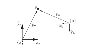 All frames defined below here are *inertial* and right handed, despite that in reality they move / rotate as we are all on planet Earth. The following example is key to understand the convention adopted here with respect to inertial frames.
**Thomas the train.**
Picture a coffee mug on a table in a train. Two people watch it: a passenger sitting in the train, and a person standing on the platform. The passenger's frame moves with the train. The platform is (close enough to) an inertial frame. Whether the train's frame is inertial depends on what the train is doing.
1. The train moves at a steady speed on a straight track. The mug sits still on the table. The passenger sees nothing happening. The person on the platform sees the mug gliding along with the train. Both descriptions are simple, and neither person needs any force beyond gravity and the table holding the mug up. A frame that moves at constant velocity is also inertial. You cannot tell you are moving without looking out the window.
2. The train brakes. The mug slides forward across the table.
* Platform view: nothing pushed the mug. It simply kept going at the speed it had, while the train slowed down underneath it. The only real horizontal force is friction from the table, which tries to drag the mug along with the slowing train. If friction is too weak, the mug keeps moving forward relative to the table.
* Passenger view: the mug was at rest, and now it moves forward. Nobody touched it. To explain that with ordinary physics, the passenger has to invent a force pushing the mug forward. This is the inertial force. It is not caused by any object; it appears only because the passenger's frame is slowing down.
3. The train speeds up. The same thing happens in reverse. The mug slides toward the back. The platform observer says the train pulled away from the mug. The passenger says a force pushed the mug backward.
4. The train goes around a curve. The mug slides toward the outside of the curve.
* Platform view: the mug tried to keep going straight while the train turned away from it. The only thing that can make the mug follow the curve is friction pulling it inward.
* Passenger view: a force pushed the mug outward. This is the centrifugal force. As with braking, it exists only in the turning frame.
5. You roll a marble across the aisle while the train is turning. The marble's path curves as it rolls.
* Platform view: the marble goes in a straight line. The train rotates underneath it.
* Passenger view: the marble seems to be steered sideways while it moves. This is the Coriolis force. It acts only on things that are moving relative to the turning frame. That is why the mug sitting still does not feel it, but the rolling marble does.
In the inertial frame there are only real forces, and the mug does what it was already doing. In the non-inertial frame, you must add inertial, centrifugal and Coriolis forces to make Newton's laws work again. These forces are bookkeeping for the frame's own motion. No object is pushing, but they correctly predict what the passenger sees. You accept that bookkeeping because the passenger's frame is the natural one for the passenger. The table, the seats and the mug's position "on the table" are all simplest to describe from inside the train.
**Lynch and Park sidestep these apparent forces by expressing body quantities in a stationary frame that coincides with the body at each instant, so every frame in the book is inertial. We will expand on this later.**
## Planar Rigid-Body Motions
We define a *single* fixed frame, called *space frame* $\{s\}$, with unit axes $x̂_s$ and $ŷ_s$.Sometimes we refer to this as the *world* frame. We also define a fixed at each instance body frame, denoted $\{b\}$, associated with the body with unit axes $x̂_b$ and $ŷ_b$. This frame is coincident with the body *at any instant*.
Lynch and Park avoid non-inertial frames on purpose. Their body frame $\{b\}$ is not a frame that rides along with the body. It is a stationary frame that happens to line up with the body-attached frame at the current instant.
* The body can accelerate. The body moves freely, and the frame attached to it moves with it.
* Velocities are always measured against inertial space.
- Every instant uses a new frame. At the next instant, $\{b\}$ is a different stationary frame, the one lined up with the body at that moment.
So every frame Lynch and Park use is inertial, and no fictitious forces appear in their derivations. Note that [physics engines make their own conventions](https://newton-physics.github.io/newton/latest/concepts/conventions.html) and many borrow from Lynch and Park but also deviate, as [spatial motion representations](/aiml-common/lectures/kinematics/spatial-motion/index) shows for twists.
In the plane, a rotation matrix $P \in SO(2)$ and a translation vector $\mathbf{p} \in \mathbb{R}^2$ describe a rigid-body configuration. The pair $(P, \mathbf{p})$ represents a body in the space frame.
All frames defined below here are *inertial* and right handed, despite that in reality they move / rotate as we are all on planet Earth. The following example is key to understand the convention adopted here with respect to inertial frames.
**Thomas the train.**
Picture a coffee mug on a table in a train. Two people watch it: a passenger sitting in the train, and a person standing on the platform. The passenger's frame moves with the train. The platform is (close enough to) an inertial frame. Whether the train's frame is inertial depends on what the train is doing.
1. The train moves at a steady speed on a straight track. The mug sits still on the table. The passenger sees nothing happening. The person on the platform sees the mug gliding along with the train. Both descriptions are simple, and neither person needs any force beyond gravity and the table holding the mug up. A frame that moves at constant velocity is also inertial. You cannot tell you are moving without looking out the window.
2. The train brakes. The mug slides forward across the table.
* Platform view: nothing pushed the mug. It simply kept going at the speed it had, while the train slowed down underneath it. The only real horizontal force is friction from the table, which tries to drag the mug along with the slowing train. If friction is too weak, the mug keeps moving forward relative to the table.
* Passenger view: the mug was at rest, and now it moves forward. Nobody touched it. To explain that with ordinary physics, the passenger has to invent a force pushing the mug forward. This is the inertial force. It is not caused by any object; it appears only because the passenger's frame is slowing down.
3. The train speeds up. The same thing happens in reverse. The mug slides toward the back. The platform observer says the train pulled away from the mug. The passenger says a force pushed the mug backward.
4. The train goes around a curve. The mug slides toward the outside of the curve.
* Platform view: the mug tried to keep going straight while the train turned away from it. The only thing that can make the mug follow the curve is friction pulling it inward.
* Passenger view: a force pushed the mug outward. This is the centrifugal force. As with braking, it exists only in the turning frame.
5. You roll a marble across the aisle while the train is turning. The marble's path curves as it rolls.
* Platform view: the marble goes in a straight line. The train rotates underneath it.
* Passenger view: the marble seems to be steered sideways while it moves. This is the Coriolis force. It acts only on things that are moving relative to the turning frame. That is why the mug sitting still does not feel it, but the rolling marble does.
In the inertial frame there are only real forces, and the mug does what it was already doing. In the non-inertial frame, you must add inertial, centrifugal and Coriolis forces to make Newton's laws work again. These forces are bookkeeping for the frame's own motion. No object is pushing, but they correctly predict what the passenger sees. You accept that bookkeeping because the passenger's frame is the natural one for the passenger. The table, the seats and the mug's position "on the table" are all simplest to describe from inside the train.
**Lynch and Park sidestep these apparent forces by expressing body quantities in a stationary frame that coincides with the body at each instant, so every frame in the book is inertial. We will expand on this later.**
## Planar Rigid-Body Motions
We define a *single* fixed frame, called *space frame* $\{s\}$, with unit axes $x̂_s$ and $ŷ_s$.Sometimes we refer to this as the *world* frame. We also define a fixed at each instance body frame, denoted $\{b\}$, associated with the body with unit axes $x̂_b$ and $ŷ_b$. This frame is coincident with the body *at any instant*.
Lynch and Park avoid non-inertial frames on purpose. Their body frame $\{b\}$ is not a frame that rides along with the body. It is a stationary frame that happens to line up with the body-attached frame at the current instant.
* The body can accelerate. The body moves freely, and the frame attached to it moves with it.
* Velocities are always measured against inertial space.
- Every instant uses a new frame. At the next instant, $\{b\}$ is a different stationary frame, the one lined up with the body at that moment.
So every frame Lynch and Park use is inertial, and no fictitious forces appear in their derivations. Note that [physics engines make their own conventions](https://newton-physics.github.io/newton/latest/concepts/conventions.html) and many borrow from Lynch and Park but also deviate, as [spatial motion representations](/aiml-common/lectures/kinematics/spatial-motion/index) shows for twists.
In the plane, a rotation matrix $P \in SO(2)$ and a translation vector $\mathbf{p} \in \mathbb{R}^2$ describe a rigid-body configuration. The pair $(P, \mathbf{p})$ represents a body in the space frame.
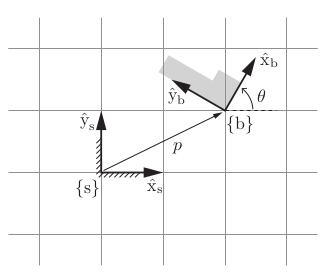 Consider a point $q$ at $[1, 1]^T$ in a frame that is rotated 60° counterclockwise and translated by $[2, 1]^T$.
In the space frame, the transformation is given by:
$$
P = \begin{bmatrix} \cos\theta & -\sin\theta \\ \sin\theta & \cos\theta \end{bmatrix}, \quad q' = Pq + \mathbf{p}
$$
Although P contains four numbers, three constraints apply. Each column of P must be a unit vector, and the columns must be orthogonal. The remaining degree of freedom is parametrized by θ. The pair (P, p) describes the orientation and position of $\{b\}$ relative to $\{s\}$.
The groups $SO(n)$ and $SE(n)$, and their algebras $\mathfrak{so}(n)$ and $\mathfrak{se}(n)$, are defined in [SO(2) as a manifold](/aiml-common/lectures/kinematics/planar-motion/so2-manifold/index). That section also has a table of every manifold used in robotics. Read it before you continue.
Any planar motion can also be interpreted as a rotation about a fixed point $\mathbf{s}$. The figure below shows such a motion.
Consider a point $q$ at $[1, 1]^T$ in a frame that is rotated 60° counterclockwise and translated by $[2, 1]^T$.
In the space frame, the transformation is given by:
$$
P = \begin{bmatrix} \cos\theta & -\sin\theta \\ \sin\theta & \cos\theta \end{bmatrix}, \quad q' = Pq + \mathbf{p}
$$
Although P contains four numbers, three constraints apply. Each column of P must be a unit vector, and the columns must be orthogonal. The remaining degree of freedom is parametrized by θ. The pair (P, p) describes the orientation and position of $\{b\}$ relative to $\{s\}$.
The groups $SO(n)$ and $SE(n)$, and their algebras $\mathfrak{so}(n)$ and $\mathfrak{se}(n)$, are defined in [SO(2) as a manifold](/aiml-common/lectures/kinematics/planar-motion/so2-manifold/index). That section also has a table of every manifold used in robotics. Read it before you continue.
Any planar motion can also be interpreted as a rotation about a fixed point $\mathbf{s}$. The figure below shows such a motion.
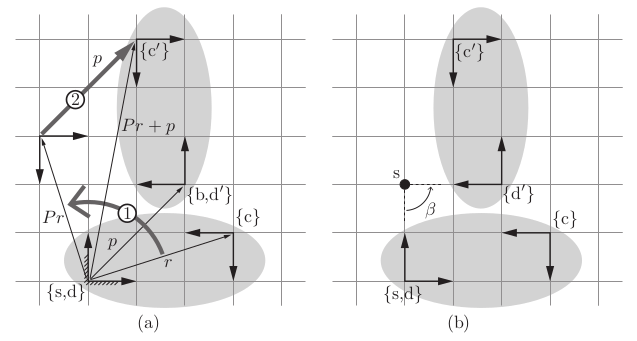 (a) The frame $\{d\}$ is fixed to an elliptical rigid body and initially coincides with $\{s\}$. A rotation by P followed by a translation by p displaces it to `\{d0\}`, which coincides with the stationary frame $\{b\}$. The pair (P, p) represents $\{b\}$ in $\{s\}$. The same transformation takes the frame $\{c\}$, also attached to the rigid body, to `\{c0\}`. Transformation 1 rotates $\{c\}$ about the origin of $\{s\}$. Transformation 2 then translates the frame by p expressed in $\{s\}$.
(b) The rotation and translation can also occur simultaneously. In this view, the displacement is a rotation of β = 90° about a fixed point s.
This is a planar example of a screw motion. The three screw coordinates $(β, s_x , s_y )$ parametrize the displacement. Here, $(s_x , s_y ) = (0, 2)$ gives the coordinates of point s, which is the screw axis out of the page, in the fixed frame $\{s\}$.
## Planar velocities and twists
Collect the rotation $P$ and the translation $\mathbf{p} = (x, y)$ into one $3 \times 3$ matrix:
$$
T = \begin{bmatrix} P & \mathbf{p} \\ 0 & 1 \end{bmatrix} = \begin{bmatrix} \cos\theta & -\sin\theta & x \\ \sin\theta & \cos\theta & y \\ 0 & 0 & 1 \end{bmatrix} \in SE(2)
$$
The matrix acts on the [homogeneous coordinates](/aiml-common/lectures/kinematics/homogeneous-coordinates/index) of the plane. A point $(x, y, 1)$ is rotated and then translated, while a free vector $(v_x, v_y, 0)$ is only rotated. The configuration of a planar rigid body is the triple $q = (\theta, x, y)$, one number per degree of freedom.
In the plane every rotation happens about the axis perpendicular to the plane, so the angular velocity is a single number, $\omega = \dot\theta$. Differentiating $P$ gives $\dot P = [\omega] P$, where
$$
[\omega] = \begin{bmatrix} 0 & -\omega \\ \omega & 0 \end{bmatrix} \in \mathfrak{so}(2)
$$
is the same skew-symmetric matrix that appears as the tangent at the identity in [SO(2) as a manifold](/aiml-common/lectures/kinematics/planar-motion/so2-manifold/index).
A *twist* packs the angular and linear velocity of the body into one object. As with frames, there are two ways to express it. The *body twist* comes from $T^{-1} \dot T$, and the *space twist* comes from $\dot T T^{-1}$:
$$
T^{-1} \dot T = \begin{bmatrix} [\omega_b] & \mathbf{v}_b \\ 0 & 0 \end{bmatrix}, \qquad
\dot T T^{-1} = \begin{bmatrix} [\omega_s] & \mathbf{v}_s \\ 0 & 0 \end{bmatrix}, \qquad
\omega_b = \omega_s = \dot\theta
$$
Both matrices belong to $\mathfrak{se}(2)$. Each is described by three numbers, collected in a twist vector $\mathcal{V} = (\omega, v_x, v_y) \in \mathbb{R}^3$:
* $\mathbf{v}_b = P^T \dot{\mathbf{p}}$ is the velocity of the body-frame origin, written in the coordinates of $\{b\}$.
* $\mathbf{v}_s = \dot{\mathbf{p}} - [\omega]\mathbf{p} = (\dot x + \dot\theta\, y,\ \dot y - \dot\theta\, x)$ is the velocity of the point of the body that is currently at the origin of $\{s\}$, written in $\{s\}$. That point may lie outside the physical body; imagine the body extended far enough to contain it.
The body twist is related to the rate of change of the configuration by
$$
\mathcal{V}_b = \begin{bmatrix} \omega_b \\ v_{bx} \\ v_{by} \end{bmatrix} = \begin{bmatrix} 1 & 0 & 0 \\ 0 & \cos\theta & \sin\theta \\ 0 & -\sin\theta & \cos\theta \end{bmatrix} \begin{bmatrix} \dot\theta \\ \dot x \\ \dot y \end{bmatrix}
$$
This relation is the starting point for [wheeled robots](/aiml-common/lectures/kinematics/wheeled-robots/index). A wheeled chassis is a planar rigid body with configuration $q = (\theta, x, y)$, and its wheels constrain its body twist. For example, a robot whose wheels cannot slide sideways must have $v_{by} = 0$. Its chassis can point anywhere and reach any position, yet at each instant it can only move forward, backward, or turn.
## References
Lynch and Park, *Modern Robotics: Mechanics, Planning, and Control* (2017)
[http://modernrobotics.org](http://modernrobotics.org)
***
[Edit this page on GitHub](https://github.com/aegean-ai/eaia/edit/main/src/aiml-common/lectures/kinematics/planar-motion/index.mdx) or [file an issue](https://github.com/aegean-ai/eaia/issues/new/choose).
(a) The frame $\{d\}$ is fixed to an elliptical rigid body and initially coincides with $\{s\}$. A rotation by P followed by a translation by p displaces it to `\{d0\}`, which coincides with the stationary frame $\{b\}$. The pair (P, p) represents $\{b\}$ in $\{s\}$. The same transformation takes the frame $\{c\}$, also attached to the rigid body, to `\{c0\}`. Transformation 1 rotates $\{c\}$ about the origin of $\{s\}$. Transformation 2 then translates the frame by p expressed in $\{s\}$.
(b) The rotation and translation can also occur simultaneously. In this view, the displacement is a rotation of β = 90° about a fixed point s.
This is a planar example of a screw motion. The three screw coordinates $(β, s_x , s_y )$ parametrize the displacement. Here, $(s_x , s_y ) = (0, 2)$ gives the coordinates of point s, which is the screw axis out of the page, in the fixed frame $\{s\}$.
## Planar velocities and twists
Collect the rotation $P$ and the translation $\mathbf{p} = (x, y)$ into one $3 \times 3$ matrix:
$$
T = \begin{bmatrix} P & \mathbf{p} \\ 0 & 1 \end{bmatrix} = \begin{bmatrix} \cos\theta & -\sin\theta & x \\ \sin\theta & \cos\theta & y \\ 0 & 0 & 1 \end{bmatrix} \in SE(2)
$$
The matrix acts on the [homogeneous coordinates](/aiml-common/lectures/kinematics/homogeneous-coordinates/index) of the plane. A point $(x, y, 1)$ is rotated and then translated, while a free vector $(v_x, v_y, 0)$ is only rotated. The configuration of a planar rigid body is the triple $q = (\theta, x, y)$, one number per degree of freedom.
In the plane every rotation happens about the axis perpendicular to the plane, so the angular velocity is a single number, $\omega = \dot\theta$. Differentiating $P$ gives $\dot P = [\omega] P$, where
$$
[\omega] = \begin{bmatrix} 0 & -\omega \\ \omega & 0 \end{bmatrix} \in \mathfrak{so}(2)
$$
is the same skew-symmetric matrix that appears as the tangent at the identity in [SO(2) as a manifold](/aiml-common/lectures/kinematics/planar-motion/so2-manifold/index).
A *twist* packs the angular and linear velocity of the body into one object. As with frames, there are two ways to express it. The *body twist* comes from $T^{-1} \dot T$, and the *space twist* comes from $\dot T T^{-1}$:
$$
T^{-1} \dot T = \begin{bmatrix} [\omega_b] & \mathbf{v}_b \\ 0 & 0 \end{bmatrix}, \qquad
\dot T T^{-1} = \begin{bmatrix} [\omega_s] & \mathbf{v}_s \\ 0 & 0 \end{bmatrix}, \qquad
\omega_b = \omega_s = \dot\theta
$$
Both matrices belong to $\mathfrak{se}(2)$. Each is described by three numbers, collected in a twist vector $\mathcal{V} = (\omega, v_x, v_y) \in \mathbb{R}^3$:
* $\mathbf{v}_b = P^T \dot{\mathbf{p}}$ is the velocity of the body-frame origin, written in the coordinates of $\{b\}$.
* $\mathbf{v}_s = \dot{\mathbf{p}} - [\omega]\mathbf{p} = (\dot x + \dot\theta\, y,\ \dot y - \dot\theta\, x)$ is the velocity of the point of the body that is currently at the origin of $\{s\}$, written in $\{s\}$. That point may lie outside the physical body; imagine the body extended far enough to contain it.
The body twist is related to the rate of change of the configuration by
$$
\mathcal{V}_b = \begin{bmatrix} \omega_b \\ v_{bx} \\ v_{by} \end{bmatrix} = \begin{bmatrix} 1 & 0 & 0 \\ 0 & \cos\theta & \sin\theta \\ 0 & -\sin\theta & \cos\theta \end{bmatrix} \begin{bmatrix} \dot\theta \\ \dot x \\ \dot y \end{bmatrix}
$$
This relation is the starting point for [wheeled robots](/aiml-common/lectures/kinematics/wheeled-robots/index). A wheeled chassis is a planar rigid body with configuration $q = (\theta, x, y)$, and its wheels constrain its body twist. For example, a robot whose wheels cannot slide sideways must have $v_{by} = 0$. Its chassis can point anywhere and reach any position, yet at each instant it can only move forward, backward, or turn.
## References
Lynch and Park, *Modern Robotics: Mechanics, Planning, and Control* (2017)
[http://modernrobotics.org](http://modernrobotics.org)
***
[Edit this page on GitHub](https://github.com/aegean-ai/eaia/edit/main/src/aiml-common/lectures/kinematics/planar-motion/index.mdx) or [file an issue](https://github.com/aegean-ai/eaia/issues/new/choose).