

 In this section you turn the posed, masked frames of stages 1 and 2 into a closed triangle mesh of your object, in meters. Stage 4 paints that mesh, and stage 5 computes its volume, mass distribution and collision shape from it.
You train two Gaussian splats on the same frames. The first is a 3D Gaussian splat (Kerbl et al., 2023), which renders photos well and is what stage 6 scores for appearance. The second is a 2D Gaussian splat (Huang et al., “2D Gaussian Splatting for Geometrically Accurate Radiance Fields”, SIGGRAPH 2024), whose primitives are flat disks, so its rendered depth lies on a surface. Both come from the gsplat library (Apache-2.0) (Ye et al., 2024). You then render the 2D splat’s depth from every training view and fuse the depth maps into a truncated signed distance field, the volumetric method of Curless and Levoy (“A volumetric method for building complex models from range images”, SIGGRAPH 1996), using Open3D (MIT license). The zero level set of that field is the mesh.
Runtime budget: about 3 minutes for 90 training frames once the session is set up. The first run in a new session adds about 9 minutes of one-time setup. These times come from a faster GPU than Colab’s T4; on a T4 expect each step to take longer.
Two splats of the same object
Both splats train for 7,000 steps at half resolution on the training frames. Frames held out in stage 1 stay out, and so do frames whose masks the stage 2 drift check flagged. The loss is the masked loss of stage 2: every pixel outside the mask takes a background color drawn at random at each step, so the only way to match it is to leave that part of the image empty. Each splat starts from the sparse points of stage 1, and its spherical harmonics grow by one degree every 1,000 steps up to degree 3. A 3D Gaussian is a blob with center and covariance . To render it, the rasterizer projects it to a 2D Gaussian with covariance , where is the view rotation and is the Jacobian of the projection at , a local affine approximation. A pixel then reads the 2D Gaussian’s value at its own position. The projection never computes where a ray meets the blob, and the blob has thickness along every axis, so there is no surface for a ray to meet. A 2D Gaussian is a disk. It has a center , two tangent directions and with scales and , and its points are To render it, the rasterizer intersects each pixel’s ray with the disk’s plane, solves for the where the ray hits it, and weights the disk by . The depth of that hit is exact, and the disk’s normal is defined. After 3,000 steps the 2D splat adds two terms to its loss. The depth distortion term pulls the disks a ray passes through toward one depth. The normal consistency term asks each disk’s normal to agree with the normal computed from the gradient of the rendered depth. The cell prints each splat’s training time, its number of Gaussians, and its PSNR over the object’s pixels in the held-out frames.Depth from each splat
A splat gives depth the same way it gives color, by blending along the ray. The 3D splat renders the expected depth , where is the depth of blob ‘s center and its blending weight. Overlapping blobs at different depths average into a depth that need not lie on any of them. The 2D splat renders the median depth instead: the depth of the hit at which the accumulated opacity along the ray first passes one half. Two numbers compare the two kinds of depth. The first is the disagreement between views. Take the object’s pixels in one training view, lift them to 3D with their rendered depth, and project them into a view three frames later. If both depth maps describe the same surface, each lifted point lands at the depth the second view rendered there. The cell prints the median and the 90th percentile of the gap in millimeters, ignoring gaps above 2 cm, which belong to points hidden in the second view. The second number is the flatness of the 3D Gaussians: the median ratio of each Gaussian’s smallest scale to its largest. The figure shows a held-out frame, the two depth maps, and the normals computed from each depth map’s gradient. A depth map that lies on a smooth surface gives smooth normals.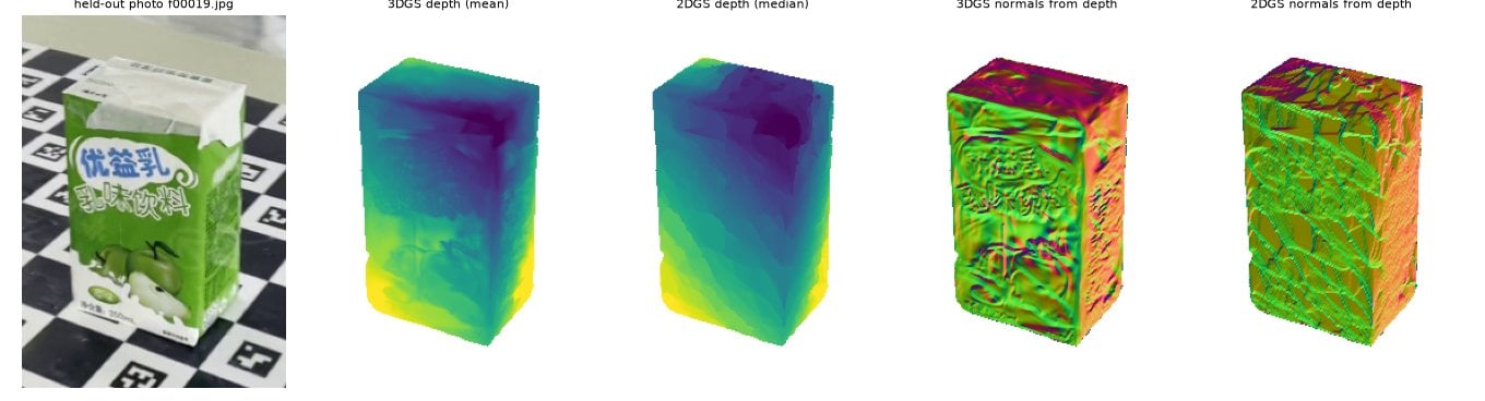
Fusing depth into a signed distance field
A truncated signed distance field stores, at every voxel of a grid, an estimate of the signed distance to the nearest surface, positive in front of it and negative behind it. Each depth map gives one estimate along its own rays. For a camera with depth map that sees at pixel and depth , and the camera says nothing about when lies more than the truncation distance behind the surface it sees. The field is the running weighted mean of these estimates over all cameras, , and the surface is its zero level set, extracted as triangles by marching cubes. Averaging many depth maps this way cancels much of their noise when they agree on one surface. The masks enter the fusion twice. Inside the mask, eroded by two pixels so that edge pixels do not count, the 2D splat’s median depth is a measurement wherever the splat is opaque. Outside the mask the ray misses the object, so you set its depth far beyond the grid: every voxel along that ray gets , empty. This carves away everything outside the object’s visual hull. A grid filled this way still has holes. No camera saw the bottom of the object, which rests on the support plane , and no camera saw the inside. After fusion you close the field. A voxel near the object that no camera measured lies behind the surface in every view, so it is inside (). Far from the object the same rule goes wrong. The grid is a cube sized by the object’s longest side, so above a long, low object, such as a hammer lying flat, it holds a large block of space outside every camera’s view. Set to inside, that block would become the largest solid in the grid and replace the object. A voxel that no camera measured is therefore inside only within the object’s box, grown by three voxels on every side, and outside beyond it. Voxels below the support plane and on the border of the grid are outside (). Last, empty voxels that cannot be reached from the border of the grid through other empty voxels are enclosed by the surface, so they are filled in as inside too. Marching cubes on a grid that is outside all around its border then gives one closed outer shell with nothing inside it. The bottom of the mesh is therefore a flat cap on the support plane. Its shape is assumed, since no camera measured it. The voxel size is of the diagonal of the object’s box, measured from the 2D splat’s masked depth in the cell below, and the truncation distance is ten voxels. A finer grid follows the depth noise more closely. A coarser one rounds off edges. The truncation matters for a depth map that lands too deep on part of a face. The voxels between the true face and that depth look empty to that camera, while every other camera sees them more than behind its own surface and says nothing, so the one bad camera digs a dent into the wall. A wider band lets the cameras that see the face correctly outvote it, at the cost of rounding parts of the object thinner than about . Before fusing, each depth map is also checked against the cameras two frames before and after it. A pixel whose 3D point lies more than five voxels behind the surface that every such neighbor sees at that spot is dropped, because the neighbors see empty space in front of it. The check cannot help when neighboring views share the same depth error, as they can on a face that only a few frames see. It finds nothing to drop, and where the shared error is deeper than the band, it stays in the mesh as a dent. On the reference object such dents are 2 to 5 mm deep and sit mostly on one of the two narrow faces. Writefuse_tsdf. It renders the 2D splat’s depth in every training view, builds the field on a uniform grid, closes it, and returns the largest connected piece of the extracted mesh. That piece must be watertight: every edge shared by exactly two triangles and every vertex surrounded by a single fan of them. Stage 5 computes the volume and inertia from it, and both need a closed surface.
Splats and mesh in the viewer
The viewer shows the centers of both splats, 50,000 of each at most, with their base colors, and the mesh, all in the world frame of stage 1. Turn the splats off to see the mesh alone, and look at its bottom: it is the flat cap on the support plane.Check
On any object the mesh must be watertight. The check also casts a fixed grid of rays along , and through the mesh’s box, kept a tenth of the box away from its faces, and counts how often each ray crosses the surface. A ray through one shell crosses it twice. A larger share of rays with more crossings means pockets or dents in the walls. A ray that runs close to a dented wall passes in and out of it, so even the reference keeps a few percent; on the reference object it fails above a limit set from the reference run, and on your object it is a warning, because an object that is not convex, such as a mug with a handle, crosses more often for real. On the reference object the check also compares the mesh with the OmniObject3D scan. The scan is in millimeters (inferred: the dataset does not state its unit) and the mesh in meters, and stage 1 recorded the transform between the scan and the world frame. Both surfaces are sampled with 200,000 points each, and the symmetric Chamfer distance is where samples the mesh and the scan. The first term is the mesh’s accuracy and the second the scan’s completeness. The check passes when is at most 1.5 times the value of the reference carton’s run, a fixed 1.24 mm. The Chamfer distance measures the mesh only if the scan sits where the object is. Stage 1 placed the scan by fitting it to the sparse points, and on a long object seen mostly from above that fit can slide the scan along the object’s length while every stage 1 check passes. So the check also fits the scan to the mesh directly, with a shift, a rotation and a scale found by iterative closest points, and prints how far the scan’s center moves and the Chamfer distance after the fit next to the one before it. On the reference object a move of more than 10 mm fails. The fusion also reports when space that no camera measured reaches a side or the top of the object’s box: part of the object was then outside the frame in every view, and the mesh there is filled in rather than measured. That fails on the reference object and is a warning on yours. On your own object there is no scan. A splat below 20 dB on the held-out frames or a mesh smaller than 5 mm or larger than 1 m prints a warning; the first usually means bad poses or masks, the second a scale problem in stage 1.Question 1. Depth from a blob and from a disk
Explain why the expected depth of a 3D Gaussian splat need not lie on any surface, and name the change in how a 2D Gaussian is rendered that makes its depth a point on a surface. Point to a region of your depth figure where the two normal maps differ. Write your answer here.Question 2. Fusing depth into a signed distance field
Explain what one depth map contributes to the field , including the rays that fall outside the mask, and why the truncation distance is needed. Point to the printed voxel size and the extent of your mesh. Write your answer here.Question 3. Closing the field
After fusion, some voxels were never measured by any camera. Explain how the fusion decides whether such a voxel is inside or outside the object, and describe an object for which that rule gives the wrong shape. Point to the part of your mesh in the viewer whose shape was assumed rather than measured. Write your answer here.References
- Kerbl, B., Kopanas, G., Leimkuehler, T., Drettakis, G. (2023). 3D Gaussian splatting for real-time radiance Field rendering. ACM Trans. Graph.
- Ye, V., Li, R., Kerr, J., Turkulainen, M., Yi, B., et al. (2024). gsplat: An Open-Source Library for Gaussian Splatting.
Found an error on this page? Report an issue.