

 A nonholonomic robot has conventional wheels that cannot slide sideways. The wheeled robots overview introduces the wheel types, the chassis configuration and the body twist used below. You will derive the kinematic model of a differential-drive robot, test its no-slip assumption on a grippy floor and on ice, and use the model for wheel odometry.
This section follows chapter 13, Wheeled Mobile Robots, of Kevin Lynch and Frank Park, Modern Robotics: Mechanics, Planning, and Control (Cambridge University Press, 2017) (Kevin M. Lynch, 2017).
Simulating the robot
The simulations use Newton, a physics engine for robotics built on NVIDIA Warp (Data Curation for Machine Lear, n.d.). The robot consists of rigid links connected by joints. Its collision shapes have a friction coefficient . Each wheel is a link on a revolute joint. Its motor tracks a commanded angular speed. The floor is a plane. The simulation has no built-in knowledge of or the no-slip condition. The chassis moves because friction at each contact pushes on the wheels. The helpers below run a simulation at 60 frames per second. They command the wheel speeds at each frame and record the chassis pose and the wheel angles. The body twist is measured from the recorded poses using the definition above. You can also record each run for the Rerun viewer. It draws the robot, paths and signals on a timeline that you can scrub.Nonholonomic robots
A conventional wheel cannot slide sideways. Suppose the chassis frame is at the midpoint of the axle between two conventional wheels. The chassis origin then never moves along : This is a Pfaffian constraint with . It restricts velocities. You cannot integrate it into a constraint on the configuration, an equation that relates , and alone. This property is called nonholonomic. At any instant, the body twist is limited to . By maneuvering, the robot can still reach any configuration , much as a driver parallel parks. Three standard models share this constraint:- Unicycle. A single upright wheel steered about its vertical axis. This is the simplest model with inputs and . The other two models reduce to it.
- Differential drive. Two independently driven wheels of radius sit at distance on either side of the chassis origin. A passive caster provides balance. Turning the left wheel at and the right wheel at gives and inverting gives the wheel speeds for a desired : and .
- Car. A car has its chassis frame at the midpoint of the rear axle. With wheelbase and steering angle , it turns at . Because is bounded, the car has a minimum turning radius . The differential-drive robot has no such limit.
Wheel speeds of a differential drive
The two formulas follow from two facts: each wheel rolls without slipping, and the chassis is rigid. A wheel of radius that turns through an angle rolls a distance along the floor. Spinning at rad/s, it moves its hub forward at . The two hubs therefore move forward at The hubs are also points of the rigid chassis, on the axle at (left) and (right). When the chassis moves with body twist , a point at lateral offset has forward speed , because the rotation adds . Turning left slows the points on the left and speeds up the points on the right: Adding the two equations cancels , and subtracting them cancels : The forward speed is the average of the two rim speeds, and the turning rate is their difference divided by the distance between the wheels. Solving the hub equations for the wheel speeds gives the inverse quoted above, and . Equal wheel speeds give and : the robot drives straight at the rim speed. The simulation below checks the differential-drive model. The robot drives straight, turns left, then turns right. It first runs on a floor with friction coefficient , then on a floor with , like ice. Each turn is a half circle of radius 0.6 m at 1 m/s. This motion needs a sideways acceleration of about . The grippy floor can supply up to through friction. Ice can supply only about .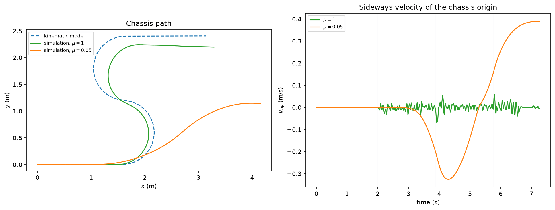
The differential-drive robot on ice. The blue line is the kinematic model’s path and the green line the path on a grippy floor; the orange line traces the robot as it skids. The right-hand panel shows .
Odometry
Odometry estimates the chassis configuration by integrating wheel motion. Every wheeled robot can measure this motion with encoders. Between two readings, let and be the changes in the wheel angles. If the wheels turn at constant speed over the interval, the chassis moves at a constant body twist per unit time. The matrix exponential gives the exact displacement in from integrating a constant twist for one unit of time. Rotate this displacement by the current heading, then add it to the current estimate to get the next estimate. Thedisplace function above performs this calculation. The odometry estimate below uses the same function.
Odometry errors accumulate because each step adds a new error to the previous ones. Some errors are systematic. Examples include a wheel radius or track width that differs from its nominal value. Calibration can remove these errors. Other errors, such as slip, are invisible to the encoders.
The experiment below begins by calibrating the effective wheel radius from a straight run. It then calibrates the effective half track from a steady circle. Both runs use the speed of the test drive. A wheel pressed into the floor rolls on a slightly smaller radius than its nominal one. It also touches the floor across the width of its tread. As a result, neither value matches the drawing. The robot then drives a long, winding path. The experiment compares the true path with three odometry estimates: nominal parameters on a grippy floor, calibrated parameters on the same floor, and calibrated parameters on ice.
For each odometry update, you apply the discrete integration on SE(2), as described in calculus on Lie groups.
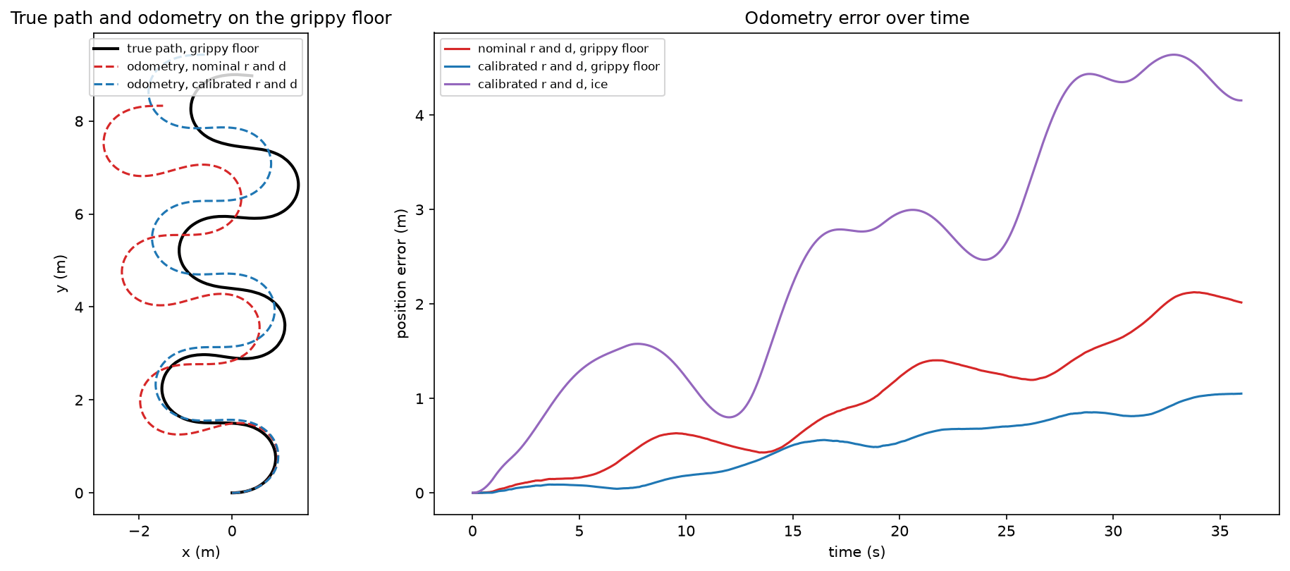
The winding drive on the grippy floor. The orange line is the true path and the blue line the calibrated odometry estimate; the right-hand panel shows their distance over time.
Further topics
Chapter 13 of Lynch and Park also covers the controllability of nonholonomic robots, including why a car can parallel park even though it cannot move sideways. It discusses motion planning under nonholonomic constraints, including shortest paths for a car with a minimum turning radius. It also treats feedback control for tracking a reference trajectory and mobile manipulation, where an arm is mounted on a wheeled base. The planning lectures in this course cover path planning for mobile robots.References
- Kevin M. Lynch, F. (2017). Modern Robotics.
- (n.d.). Data Curation for Machine Learning.
Found an error on this page? Report an issue.