

 An omnidirectional robot can move its chassis in any direction while rotating. The wheeled robots overview introduces the wheel types, the chassis configuration and the body twist used below. You will derive the wheel speeds that produce a given body twist, . You will then compare them with a physics simulation of a mecanum robot.
This section follows chapter 13, Wheeled Mobile Robots, of Kevin Lynch and Frank Park, Modern Robotics: Mechanics, Planning, and Control (Cambridge University Press, 2017) (Kevin M. Lynch, 2017).
Omnidirectional robots
Place wheel at in . Its driving direction is at angle from . Its radius is , and its free sliding direction is at angle from the driving direction. Chassis motion gives the wheel center a linear velocity. The motor must produce only the component along the driving direction. The rollers absorb the remaining component. From this relation, you can express the driving angular speed of wheel as a linear function of the body twist: Stacking one row for each wheel gives . When has rank 3, every body twist has a corresponding set of wheel speeds. This property makes the robot omnidirectional. With more than three wheels, has more rows than columns. Wheel speeds outside the form cause the wheels to fight each other and skid. The code below builds from the wheel geometry for two standard designs. The first uses three omniwheels spaced apart at distance from the center. The second uses four mecanum wheels at .- To move along , all four wheels drive forward at the same speed.
- To move along , wheels 1 and 3 drive backward, while wheels 2 and 4 drive forward.
- To rotate counterclockwise, wheels 1 and 4 drive backward, while wheels 2 and 3 drive forward.
Simulating the robot
The simulations use Newton, a robotics physics engine built on NVIDIA Warp (Data Curation for Machine Lear, n.d.). The robot consists of rigid links connected by joints. Its collision shapes have a friction coefficient . Each wheel is a link on a revolute joint, and its motor tracks a commanded angular speed. The floor is a plane. The simulation has no built-in knowledge of or the no-slip condition. Friction at each contact pushes on the wheels and moves the chassis. The helpers below run a simulation at 60 frames per second. They command the wheel speeds at each frame and record the chassis pose and the wheel angles. The body twist is measured from the recorded poses using the definition above. You can also record each run for the Rerun viewer. It displays the robot, logged paths and signals on a single timeline that you can scrub.The mecanum robot in simulation
The simulated robot has four mecanum wheels, each with twelve passive rollers, at m and m. You command the chassis through four phases of three seconds each: forward, sideways, turning in place, and a combination of all three. At every frame, the wheel speeds come from with the commanded twist.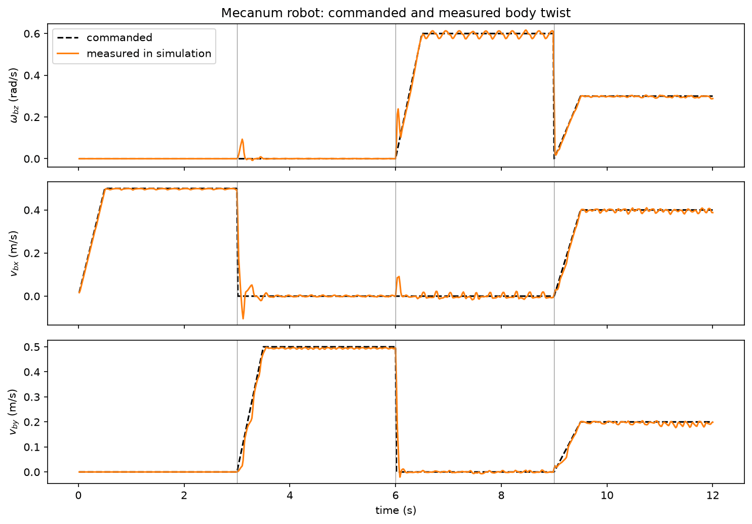
The mecanum robot driven by . Scrub the timeline to follow the four phases; the right-hand panels show the commanded and measured components of the body twist.
References
- Kevin M. Lynch, F. (2017). Modern Robotics.
- (n.d.). Data Curation for Machine Learning.
Found an error on this page? Report an issue.