

 The chapter so far built the machinery in the abstract: the configuration space a robot lives in, the homogeneous coordinates that let a single matrix carry both rotation and translation at once, and the rotation representations that describe orientation. This section spends that machinery on a real six-axis arm, the AR4, and works through its forward kinematics (where the hand is, given the joint angles) and inverse kinematics (which joint angles place the hand at a desired pose).
Forward and inverse kinematics of the AR4 arm, by Chris Annin (Annin Robotics), whose open-source Denavit-Hartenberg models this section builds on.
The AR4 is an open-source arm with six revolute joints. Its configuration is a single vector of joint angles, a point in a six-dimensional configuration space bounded by the mechanical joint limits. Everything below is a function of that vector.
Denavit-Hartenberg parameters
A serial arm is a chain of links connected by joints. The Denavit-Hartenberg (DH) convention is the standard bookkeeping that attaches a coordinate frame to every link and summarises the geometry between consecutive frames with just four numbers per joint: the joint angle , the link offset , the link length , and the link twist . Each row of the table is nothing more than one homogeneous transform, so the whole arm is the product of six of the matrices from the homogeneous coordinates section. There are two DH conventions in common use, and the AR4 ships with both. Standard (classic) DH places each frame at the far end of its link; modified (Craig) DH places it at the near end. They describe the same physical arm and produce the same hand pose, but the numbers in the table differ, which is a frequent source of confusion when reading someone else’s model. The table below is the AR4 in the standard convention. The column is the fixed offset added to each joint variable, so the joint you command is and the angle the transform sees is .The DH transform
For the standard convention, the transform from frame to frame is a rotation about by , a translation along by , a translation along by , and a rotation about by , composed into the single matrix The top-left block is the orientation of link relative to link ; the last column is its position. This is exactly the homogeneous transform of the earlier section, specialised to the four DH numbers.Forward kinematics
Forward kinematics is the product . It maps a point in the six-dimensional configuration space to a single hand pose: a position and an orientation in the world frame. The map is smooth and, for a given arm, exact, so it is the natural ground truth to check an implementation against. At the home configuration the AR4 hand sits at a known point, which is what the next cell confirms.End-effector orientation
The hand pose carries an orientation as well as a position. The rotation block of can be read out in any of the rotation representations; a Euler triple (yaw, pitch, roll) is convenient because it matches how the arm’s controller reports the tool pose.Seeing the arm
Reading a pose off a matrix is abstract; drawing the arm makes the chain concrete. Taking the running product gives the position of every joint, and connecting them in order traces the physical links from the base to the hand. The figure shows the AR4 at its home pose and at a bent configuration.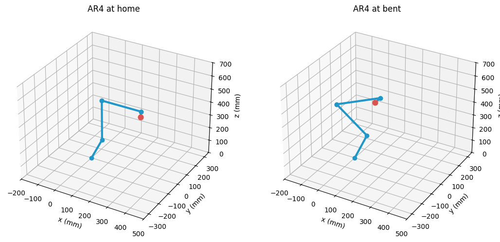
Standard versus modified DH
The same arm, written in the modified (Craig) convention, uses a different table because each frame sits at the near end of its link instead of the far end, and the twist and length of the previous link move into each row. The transform is reshaped accordingly. Neither table is more correct; they are two encodings of one geometry, and each reproduces the hand pose its own spreadsheet reports. Recognising which convention a model uses is the practical skill, because mixing the two silently produces a wrong arm.Inverse kinematics
Forward kinematics is a direct product; inverse kinematics is the harder inverse question, and for a general pose it has no unique answer. The AR4 has a spherical wrist, the last three joint axes intersecting at a point, which classically lets the problem decouple: the wrist-centre position fixes the first three joints, and the remaining orientation fixes the last three. Here the same solution is reached by iteration, which needs no special-case algebra and generalises to arms without that structure. Starting from a guess, each step measures the pose error, both the position gap and the orientation gap as a rotation vector, and corrects the joints along the Jacobian of the forward map. The loop converges to joints whose forward kinematics reproduce the target, which is the check applied below. Both steps use operations from calculus on Lie groups. The orientation error uses the left minus on SO(3), , and is expressed in the world frame (Solà eq. 28) (Solà et al., 2018). You construct the Jacobian in the same way. For each column, nudge one joint, take the left minus between the new and old orientations, then divide by the nudge. The angular rows therefore form the left Jacobian of the forward map (Solà eq. 44). Each update is a Jacobian step in the tangent space, where errors are ordinary vectors.From joint angles to motor steps
Kinematics stops at joint angles, but the arm is driven by stepper motors, and the firmware speaks in steps. Each joint has its own reduction, the product of gearbox and pulley ratios, and a fixed number of microsteps per motor revolution, so a commanded angle becomes an integer count of steps. The same joint vector that produced a hand pose becomes the integer step counts the controller sends to the drivers.From the model to the real robot
Everything here was derived from the arm’s Denavit-Hartenberg table: a compact, convention-defined summary of the geometry. The AR4 kinematics lab takes the same arm from the other direction, parsing its as-built URDF, and reconciles the two descriptions to see where they agree and where a real millimeter-scale discrepancy hides.References
- Solà, J., Deray, J., Atchuthan, D. (2018). A micro Lie theory for state estimation in robotics. arXiv [cs.RO].
Found an error on this page? Report an issue.