Vectors and Reference Frames
A vector is a geometric quantity that possesses both magnitude and direction. Vectors are inherently coordinate-free and only acquire specific numerical values when expressed in a particular coordinate frame. For example, a velocity vector may be in frame , but its representation will differ in another frame . Points are also represented as vectors, with their coordinates defined relative to the origin of a reference frame as shown in (see figure above).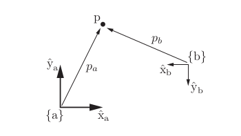
Planar Rigid-Body Motions
In the plane, a rigid-body configuration is described by a rotation matrix and a translation vector . Together, this pair allows us to represent the configuration of a body in the space frame, change the frame in which vectors are represented, and displace a point or frame through rotation and translation. For example, consider a point at in a frame that is rotated 60° counterclockwise and translated by as in (see figure above).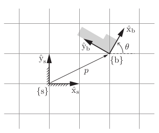
\{b\} relative to \{s\}.
Any planar motion can also be interpreted as a rotation about a fixed point . Lets look at planar motion of (see figure above).
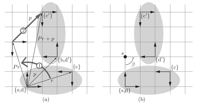
\{d\}, fixed to an elliptical rigid body and initially coincident
with \{s\}, is displaced to \{d0\} (which is coincident with the stationary frame \{b\}),
by first rotating according to P then translating according to p, where (P, p) is the
representation of \{b\} in \{s\}. The same transformation takes the frame \{c\}, also
attached to the rigid body, to \{c0\}. The transformation marked 1 rigidly rotates
\{c\} about the origin of \{s\}, and then transformation 2 translates the frame by p
expressed in \{s\}.
(b) Instead of viewing this displacement as a rotation followed by
a translation, both rotation and translation can be performed simultaneously. The
displacement can be viewed as a rotation of β = 90° about a fixed point s.
This is a planar
example of a screw motion. The displacement can therefore be parametrized
by the three screw coordinates , where denotes the
coordinates for the point s (i.e., the screw axis out of the page) in the fixed
frame \{s\}.
Rotations and Angular Velocities in 3D
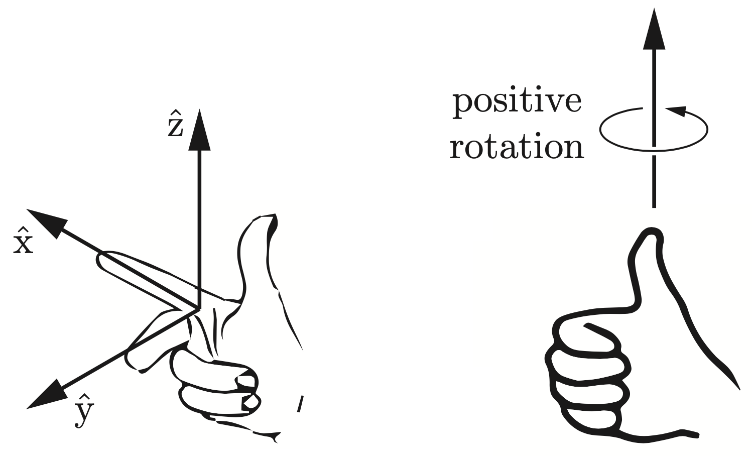
Lets expand now to the general 3D case as shown in (see figure above). By convention here all coordinate systems are right handed - a rule that is shown in (see figure above) and that where the unit axis satisfy .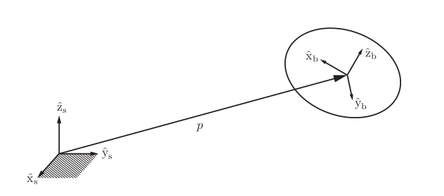
Angular Velocities
Suppose that a frame with unit axes is attached to a rotating body. Let us determine the time derivatives of these unit axes. Beginning with , first note that is of unit length; only the direction of can vary with time (the same goes for and ). If we examine the body frame at times and , the change in frame orientation can be described as a rotation of angle about some unit axis passing through the origin. The axis is coordinate-free; it is not yet represented in any particular reference frame. In the limit as approaches zero, the ratio becomes the rate of rotation , and can similarly be regarded as the instantaneous axis of rotation.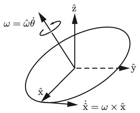
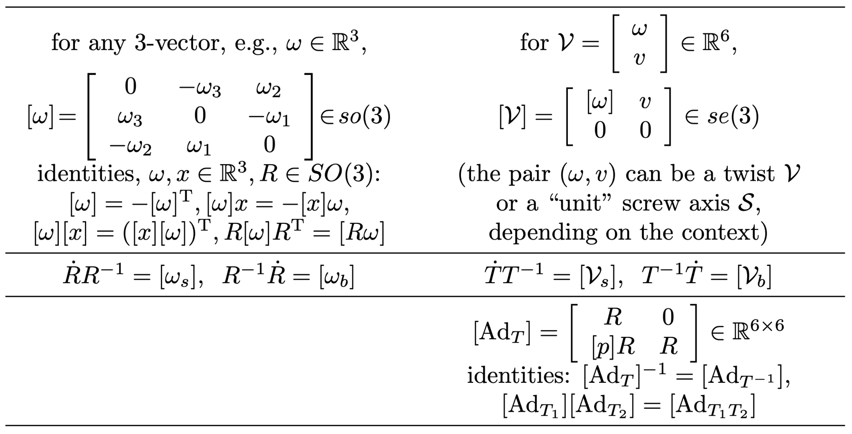
Given a vector , defineThe matrix is a skew-symmetric matrix representation of ; that is,
.The set of all real skew-symmetric matrices is called .
Exponential Coordinate Representation of Rotations
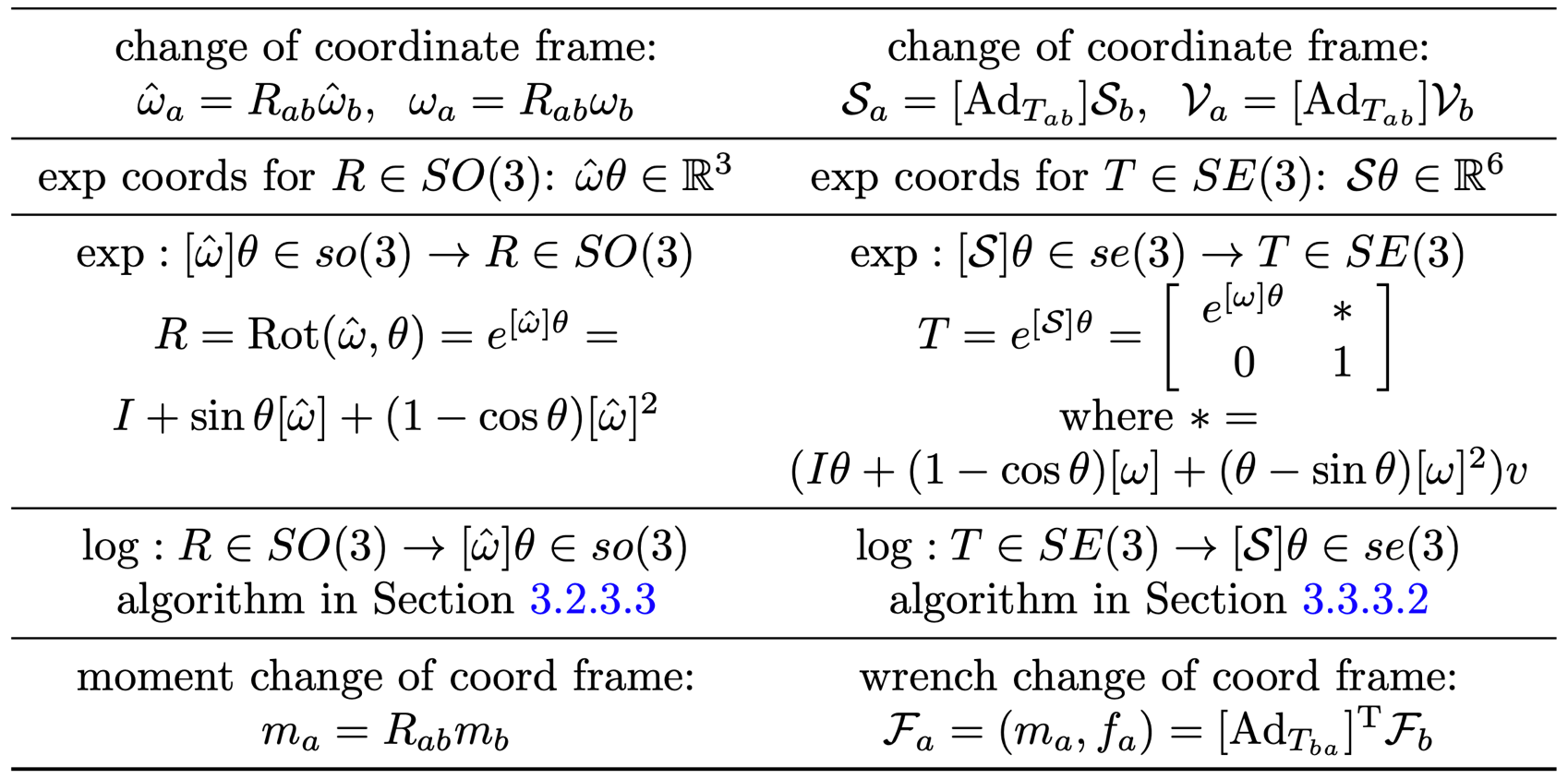
Rodrigues’ formula provides a way to compute rotation matrices: This formula defines the exponential coordinates of rotation. Any rotation can be expressed as: The logarithm of a rotation is the inverse of the matrix exponential. If , then:Rigid-Body Motions in SE(3)
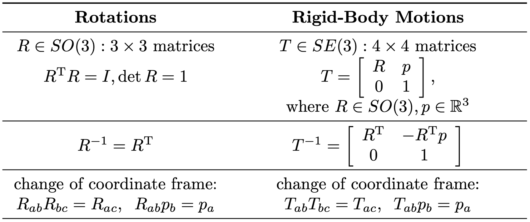
Rigid-body motions in three-dimensional space are described using homogeneous transformation matrices: This matrix encodes both rotation and translation. The inverse of a homogeneous transformation matrix is given by: Composing transformations is straightforward:Twists (Spatial Velocities)
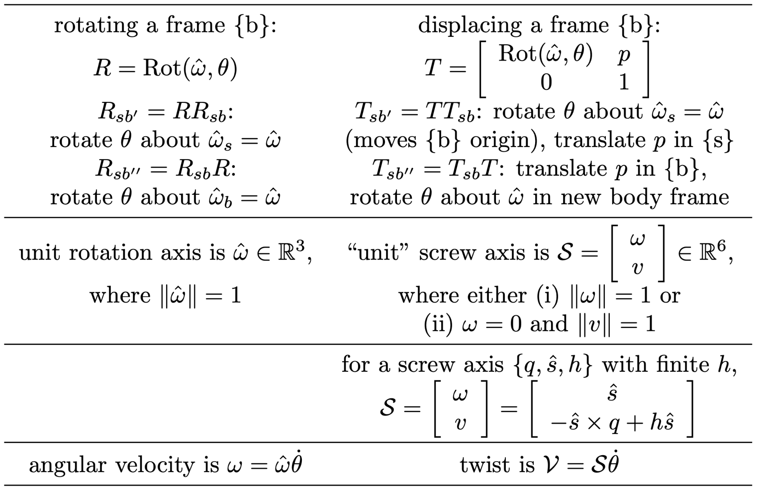
A twist is a six-dimensional vector that combines angular and linear velocity: The matrix representation of a twist is: Body and spatial twists are defined as follows: and . The adjoint operator is given by:Exponential Coordinates for Rigid Motions
Exponential coordinates provide a compact way to describe rigid motions. Let be a screw axis. The transformation is given by: where Given a transformation , the matrix logarithm is used as follows: Thus, .Wrenches (Spatial Forces)
A wrench is a six-dimensional vector that combines force and torque: Here, is the force and is the torque (moment). Coordinate transformations for wrenches are given by:Summary of rotation and motion representations
Other representations
This section borrows heavily from the book Introduction to Autonomous Robots.