Camera Calibration
Introduction
Camera calibration is the process of estimating the intrinsic and extrinsic parameters of a camera, focal length, optical center, and lens distortion coefficients, so that we can accurately map 3D points in the world to 2D image coordinates. Calibration is a prerequisite for any vision-based robotics pipeline: visual odometry, SLAM, object pose estimation, and 3D reconstruction all depend on an accurate camera model. In simulation the camera is ideal (no distortion, known focal length), but real cameras always have manufacturing imperfections. This assignment gives you hands-on experience with the full calibration workflow using a real camera, and then applies the calibration to pose estimation in ROS 2.Constraints
You can use libraries like NumPy, SciPy, and PyTorch for matrix operations and optimization, but you should not use any high-level computer vision libraries that provide built-in camera calibration functions (like OpenCV’scalibrateCamera). You will implement Zhang’s method from scratch.
You may use the Kornia library and consult its source code for DLT and other camera calibration functions to guide your implementation. You should not call high-level Kornia APIs directly, but you can use helper functions such as kornia.geometry.conversions.convert_points_to_homogeneous.
PyTorch bonus: Students who implement their solution using PyTorch will receive 10 extra credit points.
You can structure your code as a package using this template, or you can work within a single Jupyter notebook.
Background Reading
Study sections 13.1 and 13.2 of Peter Corke’s textbook Robotics, Vision and Control (RVC3). The book’s GitHub repo and the Chapter 13 notebook script contain reference code.Task 1: Implement Zhang’s Camera Calibration Method
You will implement Zhang’s method from scratch, including:- DLT (Direct Linear Transform) initialization, compute an initial estimate of the homography between the calibration pattern and each image.
- Closed-form intrinsic parameter extraction, recover the camera matrix from the homographies.
- Non-linear refinement, refine all parameters (intrinsics + extrinsics for each view) by minimizing reprojection error. You can implement this with stochastic gradient descent (SGD) or Levenberg-Marquardt.
Test Dataset
Use the pantelism/wide-camera-calibration HuggingFace dataset as test images. The dataset is available in Parquet format:Your Own Captures
After validating on the test dataset, repeat the calibration with your own images:- Print out the 9x7 checkerboard pattern and attach it to a rigid flat surface (cardboard or clipboard).
- Using your smartphone, laptop webcam, or a USB camera set to a fixed zoom level, capture at least 15 images of the checkerboard from different angles, distances, and orientations, as demonstrated in Fig 13.11 of RVC3.
- Ensure good, diffuse lighting; keep the pattern flat and in focus for every shot
- Disable autofocus and set a fixed focus for the duration of the calibration
- Capture from many different positions and angles, up to about 45 degrees
- Ensure the pattern fills a significant portion of the field of view and cover the entire lens area
- Avoid images where the pattern is perfectly flat/frontal, angled views provide more information
- Capture both wide shots and close-ups where the pattern is larger in the frame
-
Report the following:
- Camera matrix (focal lengths , and principal point , )
- Distortion coefficients (, , , , )
- Reprojection error (RMS, in pixels)
- Include your own captured images, not the book’s examples or the test dataset
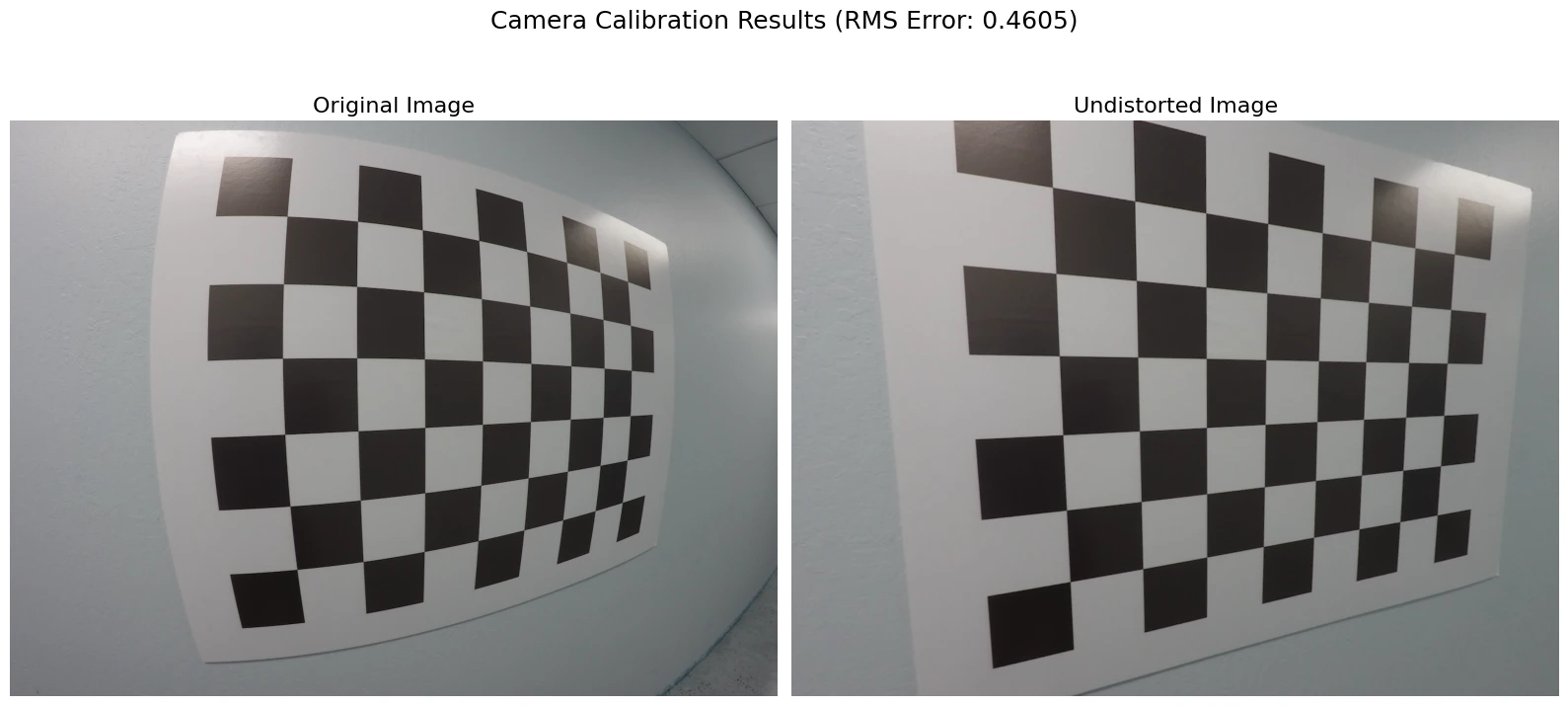
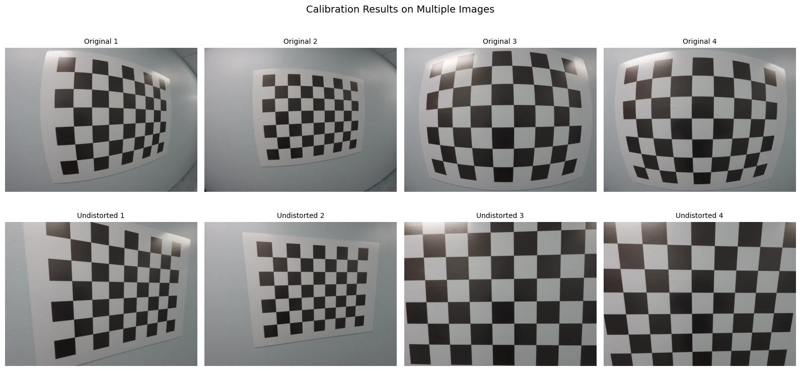
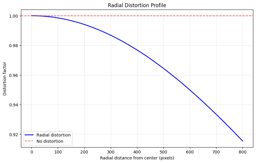
- Visualize the undistorted vs. distorted images side by side for at least 3 of your captures. Plot the radial distortion profile (distortion factor vs. radial distance from center).
Task 2: Pose Estimation with Calibrated Camera (ROS)
Now that you have calibrated your camera, use the calibration to estimate object poses.- In the Gazebo maze environment, place objects on tables (you can reuse objects from previous assignments).
-
Using OpenCV’s
solvePnPfunction (wrapped by RVC3’s Section 13.2.1 functions), estimate the relative pose of the objects from the camera. You need the 3D geometry of your objects (e.g., known cube dimensions) and corresponding 2D image detections. Alternatively, attach ArUco fiducial markers to the objects and use thecv2.arucomodule to estimate poses directly. - Establish a correspondence between a world coordinate system and the fixed objects in the scene. Use the relative pose estimates to compute the camera pose (rotation matrix and translation vector) in the world frame.
-
In ROS 2, verify how calibration parameters are published on the
/camera_infotopic. For the simulated camera, confirm the parameters match the ideal model:
Deliverables
- This section (or package) with all cells executed, showing your captured images and calibration results.
- Your from-scratch Zhang’s method implementation with DLT initialization and non-linear refinement.
- Validation: comparison table of your results vs. the OpenCV reference solution on the test dataset.
- Your own camera’s calibration parameters and a comparison with the simulated camera’s ideal parameters.
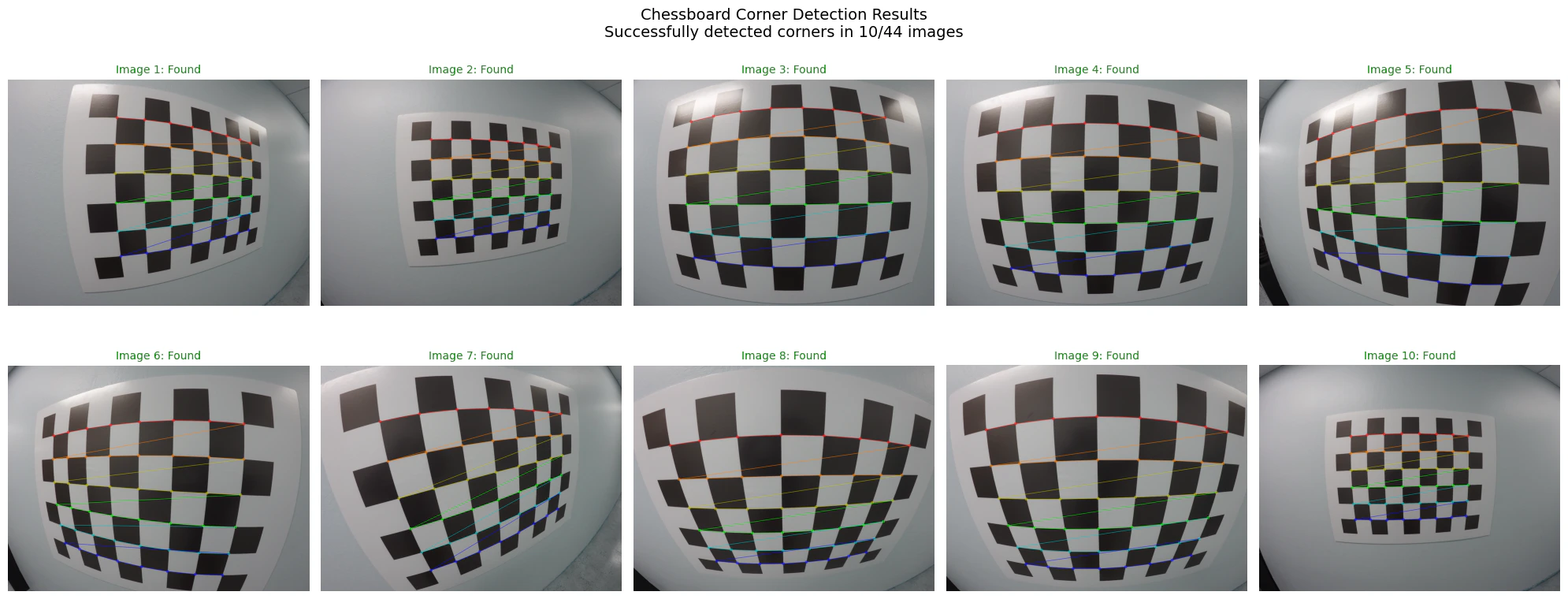
- Visualizations: detected checkerboard corners, undistorted images, radial distortion profile, and estimated object poses.
OpenCV Reference Solution
The following cells provide the OpenCV reference solution for camera calibration. Use this to validate your from-scratch implementation.