

Right-handed and left-handed frames
A right-handed frame follows the right-hand rule: point your thumb along the -axis and your index finger along the -axis, and your middle finger points along the -axis. A left-handed frame reverses one axis. Software uses both conventions, so check which one applies before you combine data from two sources. ROS 2 and its viewer RViz2 use right-handed frames. A robot’s body frame follows REP-103:The camera’s frames
In the descriptions below, imagine standing behind the camera and looking where it looks. Left and right, for the infrared sensors and for positions, mean left and right from that point of view.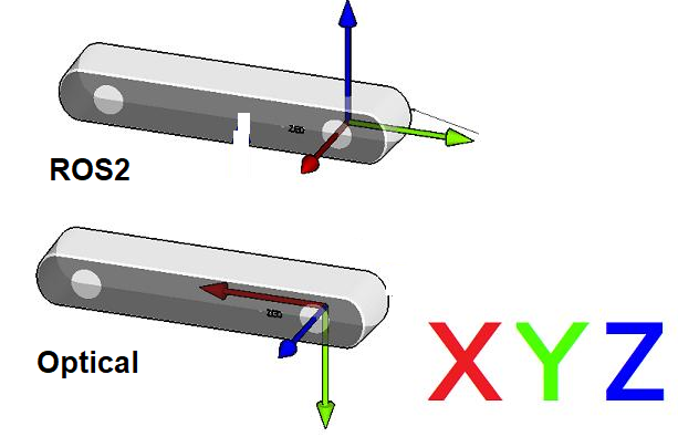 The camera frames of a RealSense camera, seen from behind.
Every sensor on the camera has two frames:
- a ROS frame, with forward, left and up, as in the table above
- an optical frame, with right, down and forward, the convention of the pinhole model
camera_link. Its origin is at the left infrared sensor (infra1). The depth frame, the left infrared frame and camera_link coincide, because depth is computed in the left infrared camera’s view. The wrapper publishes a static transform from each sensor’s frame to camera_link, and one from each sensor’s ROS frame to its optical frame.
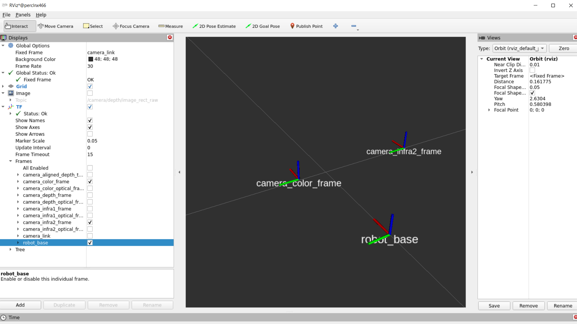 Static transforms for the RGB sensor and the right infrared sensor (infra2) of a D435i, shown in RViz2.
Transforms and extrinsics
A ROS transform message gives the pose of the framechild_frame_id in the frame header.frame_id. Applied to a point, it maps coordinates expressed in child_frame_id into coordinates expressed in header.frame_id. Mapping the other way needs the inverse. The ROS documentation calls this a transform from header.frame_id to child_frame_id, a phrase that names the two frames, not the direction in which coordinates move (geometry_msgs/Transform).
The camera reports the extrinsics between two sensors the same way. The extrinsics from sensor A to sensor B give the position and orientation of sensor A relative to sensor B. A message has two parts:
rotation: nine numbers, a rotation matrix in column-major ordertranslation: three numbers, a translation in meters
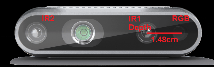 The depth and color sensors of the D435i, seen from behind the camera.
Range and bearing to a landmark
The feature-based model needs, for each landmark, its range and bearing in the robot’s frame. The frames above are what turn a detection in an image into those two numbers.From the depth image
Suppose a detector finds a landmark at pixel of the color image, for example the center of a fiducial marker. Read the depth at that pixel from the depth image aligned to the color image. The RealSense SDK and the ROS wrapper both produce this alignment, using the depth-to-color extrinsics above. The depth value is , the coordinate of the point along the optical axis. It is not the distance to the point. With the color camera’s intrinsics from the pinhole model, back-projection gives the point in the color camera’s optical frame: The transform from the camera to the robot’s base frame, published as TF from how the camera is mounted, gives the same point as . The base frame has forward and left, so the range and bearing on the ground plane areFrom the color camera alone
Without depth, a marker of known side length still gives the range. If it faces the camera and spans pixels in the image, the pinhole model gives . Solving for the marker’s full pose from its four corners, as in calibration from known points, also handles a marker seen at an angle. The bearing comes from the horizontal pixel coordinate , as before.Noise and visibility
The depth comes from the disparity , in pixels, between the left and right infrared images: , where is the infrared cameras’ focal length in pixels and is the distance between them, 50 mm on the D435i. An error in the disparity gives a depth error of about The range error therefore grows with the square of the distance. A landmark at 2 m has four times the range noise of one at 1 m. The bearing error comes from the error in the detected horizontal pixel coordinate. Near the image center it is about , and it does not grow with distance. A landmark yields a feature only if the color camera sees it, so the detector can find it, and the depth camera measures it, so it has a range. The color camera’s field of view, 69° by 42°, is narrower than the 87° by 58° depth field (D400 datasheet, Table 3-49), so the color camera sets the limit on bearing. Aligning depth to color does not widen the color image. A pixel column runs from to the color image’s width , and the bearing formula turns those two edges into bearings. With the color camera’s calibrated intrinsics, the visibility test for a camera that faces forward is With the image center in the middle of the image, , the bearing limit is half the color field of view, about .The IMU
The IMU has an accelerometer and a gyroscope. It measures how the camera moves, not where the landmarks are, so it gives no range or bearing. It helps the filter in two other ways. The gyroscope measures the turning rate, which can supplement the wheels’ estimate of in the motion model. When the robot is not accelerating, the accelerometer measures the direction of gravity, which tells you how the camera is tilted. Two different tilts matter. The first is the camera pitched down relative to the robot. That angle is fixed by the mounting, so it belongs in the rotation of the camera-to-base transform above. You measure it once, for example with the accelerometer while the robot stands on a level floor. The second is the robot standing on a slope. Then the base frame itself is tilted relative to gravity, while the map is level. Range and bearing taken in the tilted base frame are wrong: part of the landmark’s height above the floor leaks into its range, and part of its sideways offset leaks into its bearing. The accelerometer gives the roll and pitch of the base, and rotating by them gives the point in a level frame. Take the range and bearing from that level frame.Found an error on this page? Report an issue.